Valve Clearance
SAFETY FIRST: Protective gloves and eyewear are recommended at this point.
Note: The 1992 - 1997 Katana 600 models have tappet shims to adjust the valve clearance unlike the other models that have screw and locknut type adjustment.
Inspection
The engine has to be cold to check the valve clearance.
Remove the spark plugs. See the Spark Plugs topic for more information.
Remove the cylinder head cover. See the Cylinder Head Cover topic for more information.
Remove the right side bodywork panels. See the Side Fairings topic for more information.


Loosen the five signal generator cover bolts with a 5 mm Allen. Remove the bolts. The forward most bolt has a sealing a sealing washer.
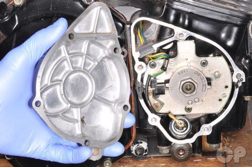
The 1988 - 1995 models have a different looking signal generator rotor from the 1996 and newer models shown below.


Remove the generator cover and gasket.


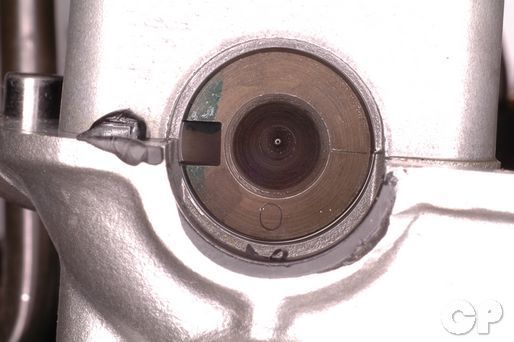
Turn the crankshaft clockwise with a 19 mm socket or wrench until the T mark on the signal generator rotor lines up with the pickup coil as shown.
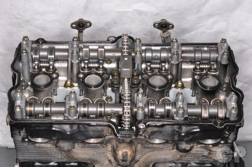
The valve clearance should be checked when the cam lobe for the valve being checked either faces up or to the side away from the rocker arm. Do not inspect the valve clearance when the lobe is against the rocker arm.
The notches on the camshafts will indicate when which valves should be checked. To get a correct reading the notches must be even with the cylinder head cover mating surface.


To move the notches 180° to the other position you must turn the crankshaft clockwise 360°.
The cylinders are numbered 1, 2, 3, and 4 left to right when looking at the engine from above and behind.
| Valve | Camshaft Position |
| Cylinder #1 Ex. | Notches face out |
| Cylinder #1 In. | Notches face out |
| Cylinder #2 Ex. | Notches face out |
| Cylinder #2 In. | Notches face in |
| Cylinder #3 Ex. | Notches face in |
| Cylinder #3 In. | Notches face out |
| Cylinder #4 Ex. | Notches face in |
| Cylinder #4 In. | Notches face in |


Check the valve clearance as noted by the table. The proper clearance reading is indicated by a slight drag on the feeler gauge. If the valve clearance is out of specification it must be adjusted.
Record tappet clearance readings on the shim type models.
| ITEM | STANDARD mm (in) | |
| Valve clearance (when cold) Screw and lock nut type |
IN. | 0.10-0.15 (0.004-0.006) |
| EX. 600 | 0.10-0.15 (0.004-0.006) | |
| EX. 750 | 0.18-0.23 (0.007-0.009) | |
| Tappet clearance (when cold) Shim type 600 1992 - 1997 |
IN. | 0.10-0.20 (0.004-0.008) |
| EX. | 0.15-0.25 (0.006-0.010) | |
Adjustment
Screw and Locknut Type
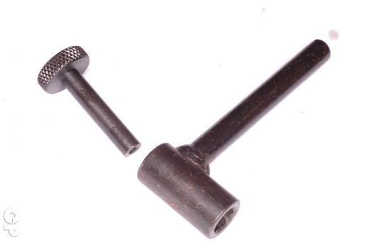
Use a valve adjuster tool to adjust the valves.
Order This Tool Here! http://www.repairmanual.com/items/17/14689
Special Tool- Valve Adjuster Driver: 09917-14910
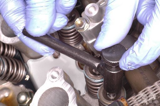
Place the wrench part of the adjuster tool over the locknut, and loosen the locknut. If the valve clearance is too tight back out the valve adjusting screw with the valve adjustment tool. If the clearance is too loose turn in the valve adjusting screw until there is a light drag on the feeler gauge. Hold the adjusting screw locknut in place with the wrench part of the tool to make sure it doesn't interfere with the adjustment. Hold the adjuster in place when you tighten the locknut. Always recheck the clearance after tightening the locknut. Also, recheck after turning the engine over a full 360°.
(Specification for adjusting screw locknut torque is 10 N-m or 7 lb-ft)
Tappet Shim Type (1992 - 1997 Katana 600)


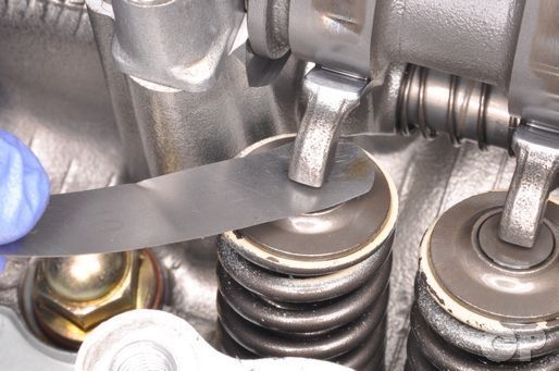
Use a flat base screw driver or similar tool to push the rocker arm to the side.
Remove the tappet shim/s of the valve/s whose clearance is not within specification using a magnet. Pay careful attention as to which valve each shim is came from or the process will have to be done over.
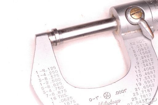
Measure the valve shims with a micrometer and record the size next to the valve clearance you took earlier for that valve.
Calculate the new shim thickness using this equation.
A= (B - C) + D
A. New shim thickness
B. Recorded valve clearance
C. Specified valve clearance
D. Old shim thickness
The smallest shim is 2.30 mm and the largest is 3.50 mm. The shims come in increments or 0.05 mm. The shims should be labeled in hundredths of millimeters. A 240 shim should be 2.4 mm thick.
Example
Recorded clearance = 0.28 mm
Specified valve clearance 0.10 - 0.20 mm
Old shim thickness 2.70 mm
(0.28 - 0.10) + 2.7 = 288
(0.28 - 0.20) + 2.7 = 278
New shim thickness 285 or 2.85 mm
Install the signal generator cover with a new gasket.


Insert the signal cover bolts. Install a new sealing washer with the forward most bolt. Tighten the bolts to specification with a 5 mm Allen.
(Signal Generator Cover Bolt Torque: 3 N-m or 2 lb-ft)
Install the cylinder head cover. See the Cylinder Head cover topic for more information.
Install the spark plugs. See the Spark Plugs topic for more information.
Install the fuel tank. See the Fuel Tank topic for more information.
Copyright - Cyclepedia Press LLC

Note: If you are viewing this document offline be sure to visit the latest version online at http://www.cyclepedia.com before attempting any repairs. Updates are made without notice.